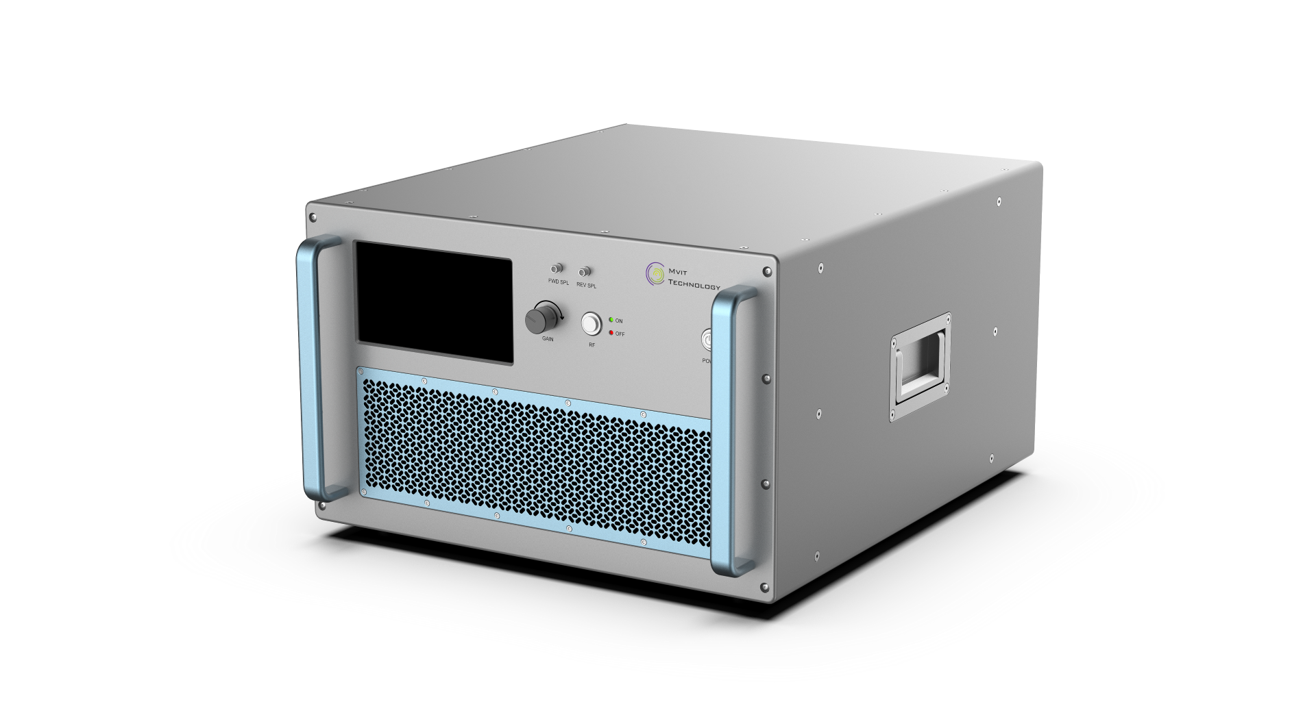
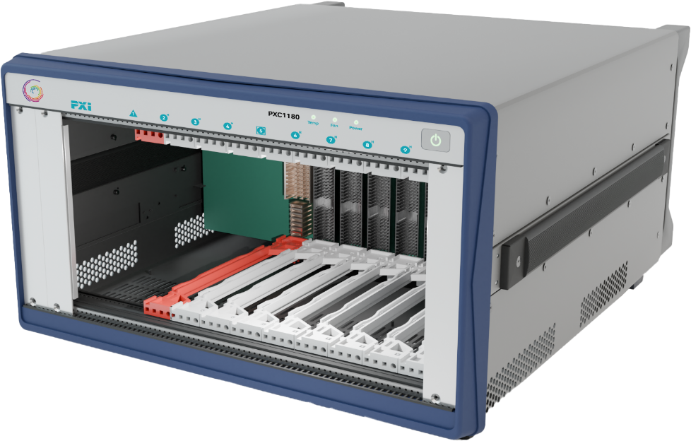
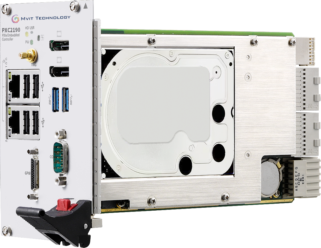
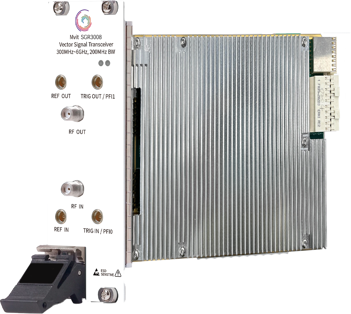
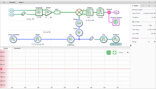
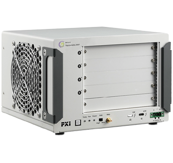
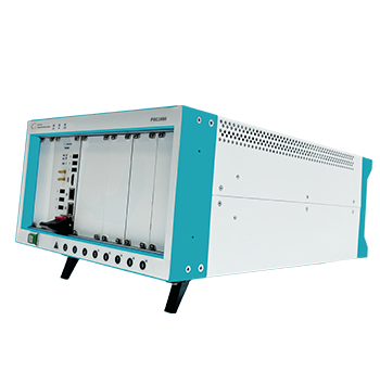
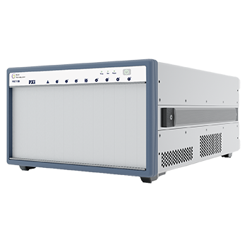
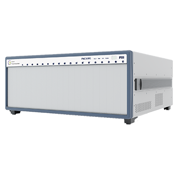
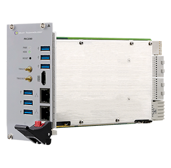
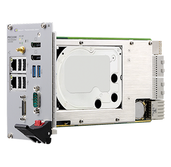
The microwave signal source test system is built on a mature and stable PXI platform, with all functions integrated within a custom PXI chassis, as shown in the diagram below. In this setup, the PXIe controller is placed in the controller slot (Slot 1) and is responsible for controlling each module to operate independently. It also analyzes, processes, and displays the data collected from each module.
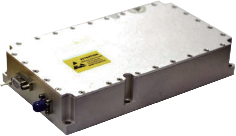
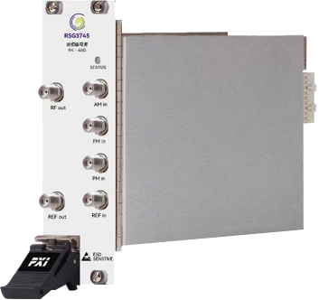
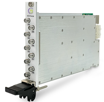
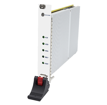
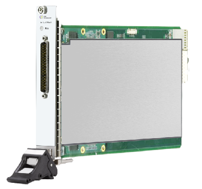
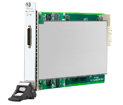
Each microwave signal source occupies 2 PXIe slots, with a total of 4 microwave signal sources occupying 8 slots. The phase-locked amplifier module communicates with the controller via the UART protocol and is securely mounted within the custom chassis through dedicated mounting holes.

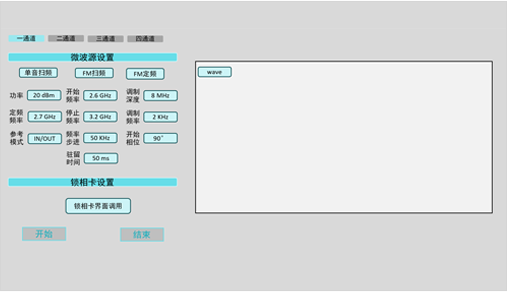
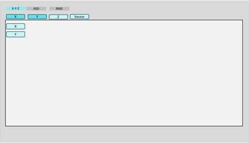
When the system is in operation, each microwave signal source module communicates with the controller via the PXIe bus. The controller sends software commands to the microwave signal sources to emit RF signals and, using the UART protocol, controls the phase-locked amplifier module to collect data. The data collected by the phase-locked amplifier is first stored in the onboard FIFO buffer and then transferred to the controller via the PXIe bus. The controller processes, analyzes, displays, and stores the data. The PXIe bus supports a maximum data bandwidth of 24 GB/s, which fully meets the data bandwidth requirements when all modules are operating simultaneously. Furthermore, each module can operate independently without affecting the others.
The entire test system is housed in a custom chassis, with the front panel divided into functional areas based on customer requirements, including microwave signal source output ports, phase-locked amplifier input ports, common communication ports (USB, Ethernet), video ports, etc.
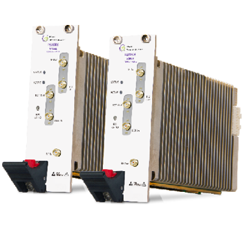
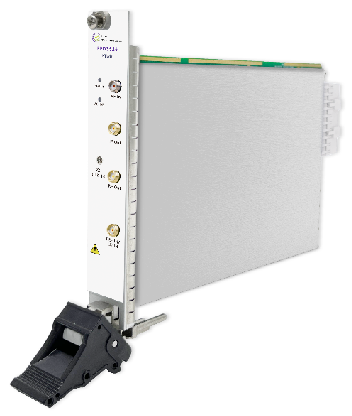
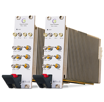
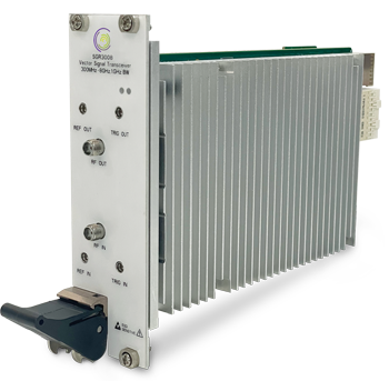
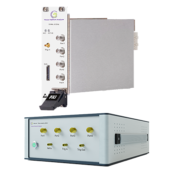
Inside the custom chassis, the system consists of:
.png)
.png)
.png)
.png)
